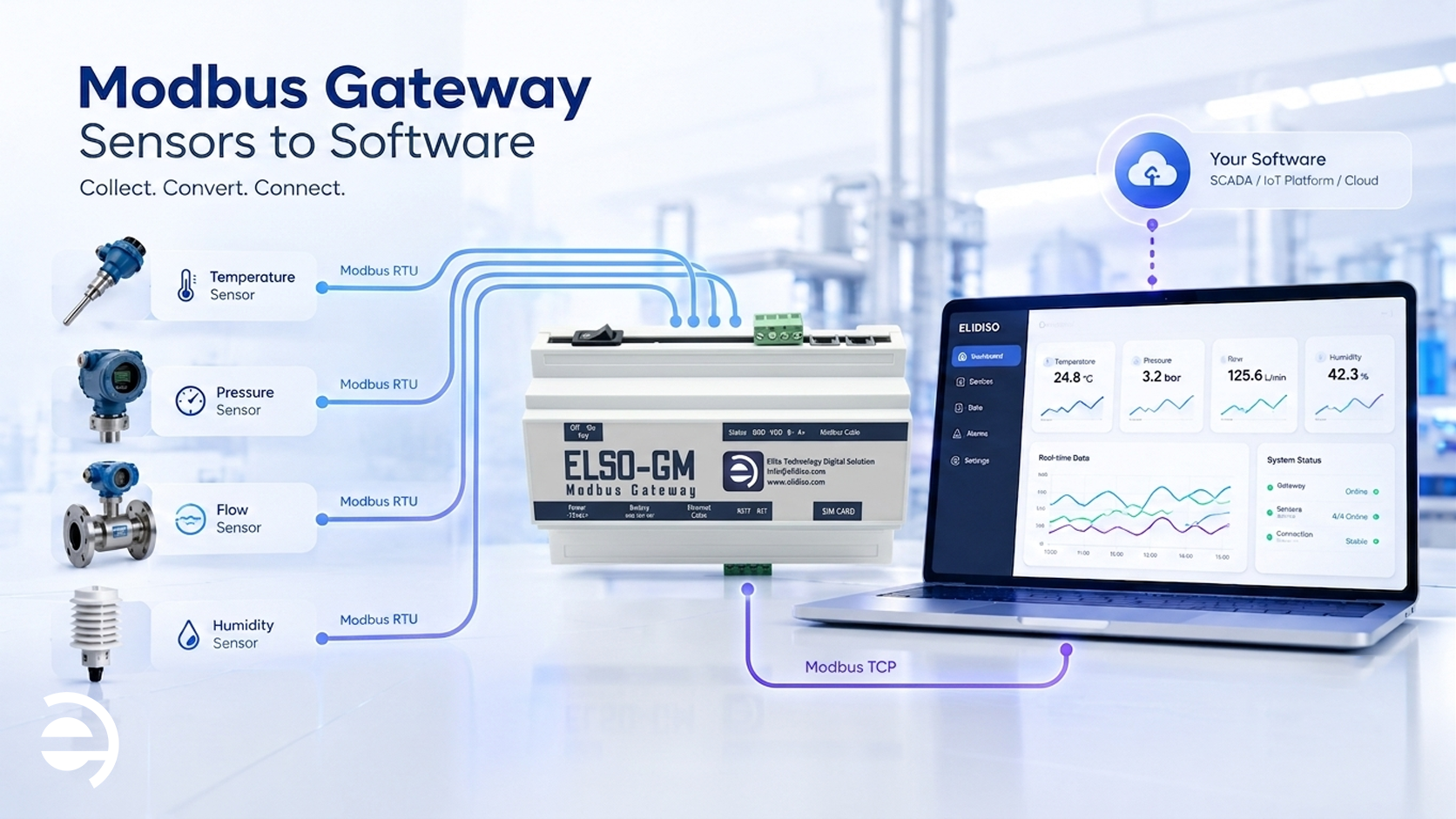
If you have deployed, or are evaluating, a Modbus-based environmental monitoring system, you will have encountered the term Modbus gateway at some point in the architecture conversation. It sits between your sensors and your monitoring software, and without it, the data your sensors collect never reaches the platform where your team can act on it. Yet for many facility managers and operations teams, exactly what a Modbus gateway does, and why it is essential how it remains unclear.
This guide explains what a Modbus gateway is, how it works within an industrial monitoring system, the different types available, and what to look for when selecting one for your facility.
What Is a Modbus Gateway?
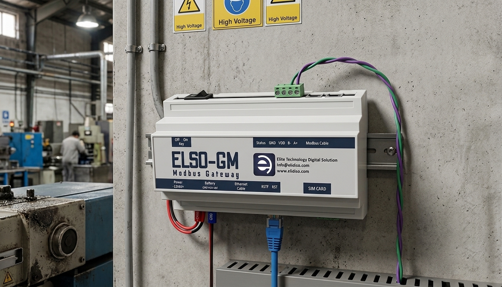
A Modbus gateway is a hardware device that acts as a protocol bridge, converting data from one communication format to another so that devices using different protocols can exchange information. In the context of industrial IoT and environmental monitoring, a Modbus gateway typically performs one core function: it converts data from Modbus RTU, the serial communication protocol used by wired sensors, into Modbus TCP or another IP-based format that can be transmitted over an Ethernet or Wi-Fi network to a monitoring platform.
In plain terms: your sensors speak one language (Modbus RTU over RS-485 wiring), your monitoring software speaks another (IP-based network communication), and the Modbus gateway translates between them, seamlessly and in real time.
Why Is a Modbus Gateway Necessary?
To understand why a Modbus gateway is necessary, it helps to understand the architecture of a Modbus sensor network. Modbus RTU sensors are wired in a daisy-chain topology along an RS-485 bus, a two-wire serial communication line that can extend up to 1,200 meters and connect up to 247 devices. This is an excellent architecture for industrial environments: robust, noise-resistant, and proven over decades of deployment.
The limitation is that RS-485 and Modbus RTU are serial protocols, they cannot natively communicate over an IP network. Your monitoring software, on the other hand, operates in the IP world, so it receives data over Ethernet, processes it through a web interface, and delivers alerts via email or SMS. Without a Modbus gateway to bridge these two worlds, the sensor data has nowhere to go.
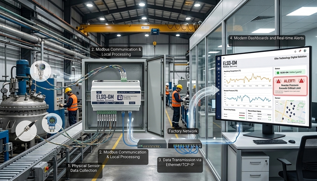
The gateway solves this by sitting on the RS-485 bus, continuously polling each sensor in sequence, collecting the latest readings, and forwarding them, translated into Modbus TCP or another IP protocol, to the monitoring platform over your facility’s network infrastructure.
Modbus RTU vs Modbus TCP — What’s the Difference?
Before going further, it is worth clarifying the distinction between the two Modbus variants a gateway typically handles:
Modbus RTU
Modbus RTU is the original serial implementation of the Modbus protocol. It communicates over RS-485 (or RS-232) wiring, transmits data in a compact binary format, and is polled by a master device, in this case, the gateway, which requests data from each sensor in turn. Modbus RTU is the protocol used by the vast majority of industrial sensors, including the Elidiso ELSO.NMxx sensor series.
Key characteristics: wired serial communication, compact data format, highly noise-resistant, cable runs up to 1,200 meters, up to 247 devices per bus.
Modbus TCP
Modbus TCP is Modbus adapted for TCP/IP networks, essentially the same data structure as Modbus RTU, but transmitted over standard Ethernet infrastructure rather than serial wiring. It removes the distance limitations of RS-485 and allows multiple masters to communicate with devices simultaneously, making it well-suited to network-connected monitoring platforms and SCADA systems.
A Modbus TCP gateway, also called an RS485 to Ethernet gateway, performs the conversion between these two variants, making your RS-485 sensor network accessible to any IP-based monitoring system. This is the most common type of Modbus gateway deployed in environmental monitoring applications.
How a Modbus Gateway Works — Step by Step
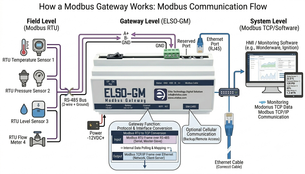
Understanding the operational flow of a Modbus gateway makes it easier to design and troubleshoot a monitoring system. Here is what happens in a typical deployment:
Step 1 — Sensors Are Polled
The Modbus gateway continuously polls each sensor on the RS-485 bus in sequence, sending a request to each sensor’s unique Modbus address and collecting the latest reading. Polling intervals are configurable, typically every few seconds to every few minutes depending on the application requirements.
Step 2 — Data Is Converted
Each sensor reading, temperature, humidity, CO₂ level, voltage, or any other parameter, is received in Modbus RTU format and converted by the gateway into Modbus TCP or another IP-compatible format. This conversion happens in real time, with no data loss and no manual intervention.
Step 3 — Data Is Transmitted to the Platform
The converted data is transmitted over the facility’s IP network, Ethernet or Wi-Fi, to the monitoring software platform. The platform receives the data, logs it with a timestamp, updates the live dashboard, and evaluates whether any readings exceed their defined alert thresholds. If a threshold is breached, the platform triggers an immediate alert to the operations team.
Step 4 — Backup Alert Delivery
A well-designed IoT Modbus gateway includes a backup communication channel, typically SMS, that ensures threshold alerts reach your team even if the primary network connection is interrupted. In critical monitoring environments such as data centers and pharmaceutical storage, this backup capability is not optional, it is the safeguard that prevents a network issue from becoming a monitoring blind spot.
How Many Sensors Can a Modbus Gateway Support?
The number of sensors a single Modbus gateway can support depends on the hardware specification. Entry-level gateways typically support 8–16 devices per bus. Mid-range and industrial-grade gateways, including the Elidiso Modbus Gateway, support up to 30 RTU sensor devices per gateway.
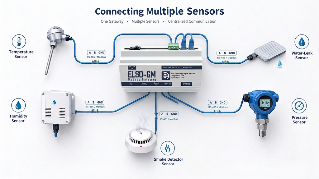
For larger facilities that require more sensors than a single gateway can accommodate, multiple gateways can be deployed, each covering a zone or floor area, and all feeding data into the same monitoring platform. This scalable architecture means a monitoring system can grow from a single room to an entire multi-building campus without requiring a change of platform or approach.
What to Look for in an Industrial Modbus Gateway
Not all Modbus gateway devices are suitable for industrial monitoring environments. When evaluating options for a facility deployment, the key criteria are:
- Device capacity — How many Modbus RTU sensors can the gateway poll on a single bus? For most facility applications, 16–30 devices per gateway is the practical requirement.
- Protocol support — Does it support Modbus TCP conversion? Does it also support SNMP for network device monitoring alongside environmental sensors?
- Backup communication — Does the gateway include an SMS backup channel for alert delivery during network outages? Critical for environments where monitoring continuity is non-negotiable.
- Industrial rating — Is the gateway rated for the ambient temperature and humidity conditions of your facility environment? A commercial-grade device will not perform reliably in industrial or GCC outdoor conditions.
- Integration compatibility — Does it integrate with your monitoring software platform and, if needed, your SCADA or BMS infrastructure via standard protocols?
- Scalability — Can additional gateways be added to expand coverage without changing the monitoring platform or workflow?
The Modbus Gateway in the Context of Industrial Network Monitoring
In a complete industrial network monitoring architecture, the Modbus gateway serves a dual role. It is the data aggregation point for the environmental sensor network, collecting temperature, humidity, air quality, and other readings from every connected sensor. And it is itself a monitored device, its connectivity status, polling health, and data transmission continuity should be visible on the same monitoring platform that receives its sensor data.
When a Modbus gateway goes offline, whether due to a power interruption, network failure, or hardware issue, the monitoring platform loses its data feed from every sensor on that gateway’s bus simultaneously. A platform that monitors gateway health alongside environmental conditions catches this scenario immediately and alerts the operations team, rather than silently losing data until someone notices the dashboard has stopped updating.
This is why Elidiso’s monitoring platform monitors both environmental sensor data and gateway network status in a single unified dashboard, because industrial network monitoring and environmental monitoring are not separate concerns. They are two layers of the same operational picture.
How Elidiso’s Modbus Gateway Fits Into Your Monitoring System
The Elidiso Modbus gateway supports up to 30 RTU sensor devices per gateway, converts Modbus RTU data to TCP/IP for transmission to the EMS monitoring platform, and includes an SMS backup channel for alert delivery during network interruptions. It integrates directly with the Elidiso ELSO.NMxx sensor series and the EMS monitoring software, forming a complete, end-to-end monitoring architecture from sensor to dashboard.
For facilities requiring Modbus TCP gateway connectivity to existing SCADA, BMS, or third-party monitoring platforms, the Elidiso gateway supports standard Modbus TCP integration via REST API, allowing it to slot into existing infrastructure without replacing legacy systems.
Contact Elidiso today to discuss your facility’s sensor network requirements and find out how the Elidiso Modbus gateway can connect your monitoring hardware to your operations platform.
Leave a Reply